Ad Circuit Board Assembly Services. Get Your Fast Online Quote Now.
Detailed Guide On Metal Core Pcb Absolute Electronics Services
This is one of many important 2 layer PCB design rules.
. It makes the copper PCB even more powerful in real applications. You must follow several design principles to avoid mistakes. Most commonly used 1oz.
For single-layer boards without layer transition to the metal plate standard process can do the required job with FR4 dielectrics where the layers are pressed and attached to the metal plate. PCB design basis and design guidelines. SMT Assembly For Engineers.
The mechanical structure is made with insulating materials laminated between layers of conductive material. If your component placement forces horizontal trace routing on one side of the board then always route traces vertically on the opposite side. Make sure that component placement is within the specifications required for the printed circuit board.
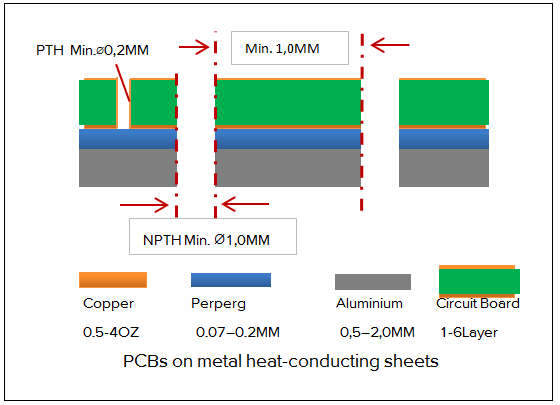
NPTH Drills Single-Sided Metal Core PCB Design Double-Sided Metal Core PCB Design with PTHs Double-sided Metal Core PCB MCPCB Manufacturing Process. To 2oz Dielectric Layer Metal Core Layer Heat Sink Types of Metal Bases used in MCPCBs Aluminum substrate The aluminum printed circuit boards offer good heat dissipation and heat transferring ability. These metal cores are etched onto the circuit boards which helps keep the heat away from the central components and wiring.
Aluminum is capable of transferring and dissipating high levels of heat easily. Designing a multilayer steel core PCB is usually a troublesome process when you dont have entry to. Metals like aluminum and copper are durable safe and long lasting and do not.
The metal core PCB exhibits good dimensional stability when compared to FR4 or CEM3 PCB. The basic structure of MCPCB comprises of the following. On each side the PCB has copper substrate or foil and the middle is sandwiched of a copper circuit board for high thermal and electric conductivity.
When aluminum PCB is heated to a temperature from 30 degree C to 140150 degree C its dimension expands between 2. Metal Core PCBs MCPCBs are designed with a metal core base which comprises one of three metals copper aluminum or steel alloy. If you want to design a new product in any of the above areas you may need to use a metal core board to control the temperature.
Metal Core PCB Capability. The IPC-2221 also explores the thermal design and ways heat dissipates from the PCBs. Other applications such as high-speed interconnect however call for extremely low relative permittivity to produce high-impedance circuits with acceptable line width and impedance tolerances.
PCB design basis and design guidelines. DFM for Metal-Core PCBs. Metal core PCBsare the result of a systematic procedure that takes great care of the metallic layers in the stackup.
Relative permittivity of substrate materials applied for RFMicrowave PCB design must be sufficiently high to meet demands of space and weight. Metal Core Pcb Design Guidelines In Altium. It requires a metal base and must adhere to certain guidelines.
Acceptability Criteria with Visual Aids. 3The metal cores are. There is a dielectric layer in-between copper foil and metal core for electric.
Laminate Substrate Guidelines. IPC Design and Acceptability Standards. Solder Mask Circuit Layer Copper layer 1oz.
Receive A Complete Quote For Fabrication Assembly And Components Entirely Online. Follow the guidelines to layout differential pairs the ground plane and high-speed signals. Choose a metal box to shield the printed circuit board.
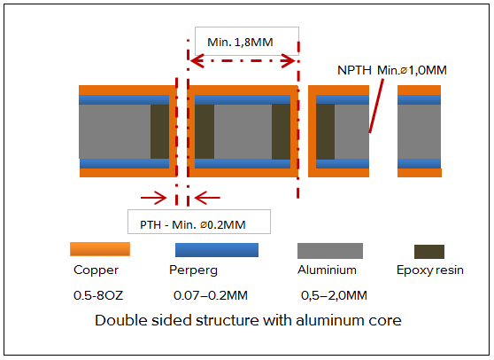
1A double-sided metal core PCB comes with a metal core between two of the boards conductor layers. Metals are good conductors of heat and electricity and hence facilitate faster heat transfer. This design is also a COB MCPCB or Chip-On-Board PCB.
Ad Start By Uploading Your BOM Get An Instant Quote For Fabrication Assembly Components. Below is a quick listing of IPC Standards that may prove helpful in PCB Design. IPC 6012 class 2 Quality and performance.
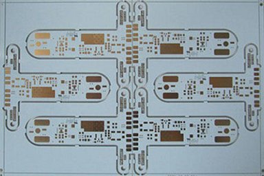
1500 New Customer Introductory Credit. You want to design Metal Core PCB you should know T-Guard for performance by Best PCB they have excellent design guide for MCPCB from single layer to double layers through Multi-layers MCPCB. The image below shows the typical.
The IPC-2221 is a general standard that envelops every aspect of the PCB design. Printed circuit board design rules and PCB layout guidelines become more complex as the number of layers in your stackup increases. Metal core PCB design including DFM follows many of the same basic design rules as typical PCBs on FR4.
Typical Thermal Conductivity of Metal Core Metal Core PCB Design Guidelines Here are some MCPCB design guidelines for reference including NPTH Drills 1 Layer Metal Core and 2 Layers Metal Core PCBs. For example a PCB design should be 002 mm larger than its nearest neighbor. T-guide for Performance T-guide for Manufacturability Single Layer IMpcb Fabrication Guideline.
Metal Core PCB Capability. Also this standard considers how conductor clearance and PDN bus layouts should be on the PCB. Metal-core boards follow a different process than typical PCB stackups involving glass-weave laminates thus they tend to carry different DFM rules.
Copper is more expensive than aluminum unlike aluminum PCB making it an economical option for some applications. The basic design of an MCPCB consists of a copper core a thermal insulating layer IC components and a solder mask. Metal PCBs made from aluminum have excellent thermal conductivity which helps keep the internal components safe.
Provide controlled impedance on all clock lines and high-speed digital signals traces with right. Use a ferrite core on the DC power cord to reduce EMI. Just like any other PCB you need to follow some basic DFM guidelines for your particular board if you want to ensure a successful fabrication run.
Here are some benefits of metal core PCBs. The MCPCB or metal core PCBs are manufactured around epoxy resin due to its adhesive capacity. PCB design and manufacturing are indivisible sides.
This specification covers qualification and performance of rigid printed boards including single-sided double-sided with or without plated-through holes multilayer with or without blindburied vias and metal core boards. Double Sided Metal Core PCB. 2The metal core merges with the conductors via the SMD and vias usually on top or at the base.
MCPCBs have many advantages over other PCB types. Manufacturing Printed Circuit Boards Since 1985. It addresses final finish and surface plating coating requirements conductors holesvias frequency of acceptance testing and quality conformance as well as.
When designing a stackup with a metal layer many key design rules in a metal core PCB should be considered. You can construct a PCB design with fewer errors and a lower cost by following these guidelines. PCB design basis and design guidelines.
You can also download it here. PCB Production Lead Time. These three metals are chosen for particular reasons.
Metal Core PCB Design Guidelines.

Ineng E9 Android Tv Box Cortex A9 Quad Core 1gb 8gb Android 4 2 Gold Android Tv Box Android 4 Android Box
Metal Core Pcb Design And Manufacturing Guidelines

Pin On Efpcb Blog

Metal Core Pcb Design Mc Pcb Design Expert With Complete Design Guide
King Credie Printed Circuit Board Pcb Manufacturing Online Quote
The Basics Of Metal Core Pcb Design And Manufacturing Nwes Blog
King Credie Printed Circuit Board Pcb Manufacturing Online Quote

Multilayer Pcb Types Of Pcb Multi Layering Pcb Design Circuit Board
0 comments
Post a Comment